DIY Crown Molding Lighting
by: Dale Cox
Check permit requirements before beginning electrical work.
How to read these diagrams.
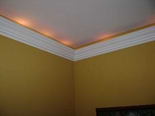
A string of small lights, like the rope lights pictured here can be placed behind a strip of crown molding to add instant warmth to any room. The lights in this project are plugged into an electrical receptacle located behind the crown molding. The power to the receptacle is drawn from the source at the room's light switch and is controlled by a new switch added in the same location.
If no wall switch exists in the room where you are adding this lighting, go here for help finding an electrical source and adding the wiring required for this project.
#1 - Plan the Molding Design
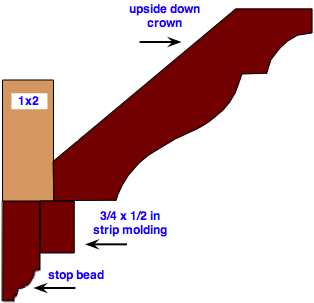
Standard 52° crown molding is used in this project. To provide sufficient space behind and conceal the lights, a 1x2 board is added to the back and the crown is hung upside down.
The crown is installed in reverse so the thicker ceiling-edge can hold the weight of the "floating" molding. It also causes the angle to be more obtuse, providing more space behind for the string. In addition to crown molding, a piece of stop bead and a small squared strip are used to add dimension to the finished profile and give the whole thing a more elegant feel.
Plan to hang the molding a minimum of 5 inches from the ceiling to allow room for installing the lights. Final placement is not set in stone but 5 to 8 inches is usually a good location. Hang it lower if you want to but don't go overboard and remember to allow for window and door casings when planning placement.
#2 - Measure and Mark the Wall
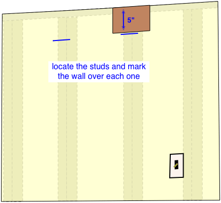
Measure and mark the wall using a board cut to the right size as a measuring tool, we use 5 inches here. First, locate the studs and mark each location a couple inches from the ceiling. To find the studs, tap across the wall with your knuckle or a small rubber hammer, and listen for a difference in the sound produced. In general, a dull sound indicates a space behind the wallboard and a sharper sound indicates a stud underneath.
With a rough idea of the location of the framing, use a drill and an eighth inch bit to bore a small hole where you expect to find the studs. If the drill passes straight through, missing the stud, keep drilling at one inch intervals until you hit wood. When you've located the framing, use the marking board to draw a straight line over each stud location as a guide for hanging the molding.
#3 - Install the Outlet Boxes
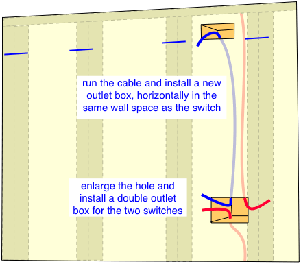
Determine a convenient place to install a new outlet box for the receptacle so it will be near the electrical source. If you're using the existing switch as a source and you can remove the box without damaging the wall, you can widen the hole and then use an old work outlet box for the two switches. If you have to damage the wall to get the old box out, you will have to use a nail-in box or one with a bracket to attach it to wood framing and then repair the wall when you're done.
For the receptacle use an old work box and locate it in the same hollow part of the wall as the existing switch box. Place the box horizontally so it will be hidden behind the new crown molding. Mark the wall for the new receptacle using the outlet box to draw the outline and then cut drywall using a drywall saw. Cut wood lath plaster with a keyhole saw or reciprocating saw. Run the new cable from the switch hole to the receptacle hole and secure the wires in the new boxes before installing them in the wall.
#4 - Install the 1x2
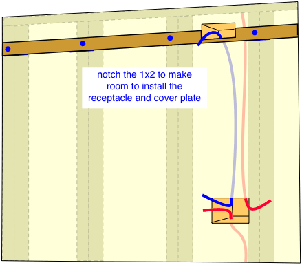
If necessary, cut a notch in the 1x2 board to allow for the outlet box before attaching it to the wall. Hold the board up and drill a pilot hole over each stud using a countersink bit so the screw heads will sink below the wood surface when it's installed. Set the bottom edge of the 1x2 on the straight lines you drew with the measuring stick and set a level on top to be sure it's straight before driving 2½ inch screws to secure it to the framing. If your walls are very thick, you may need to use 3 inch screws to attach this backer board.
#5 - Install the Receptacle
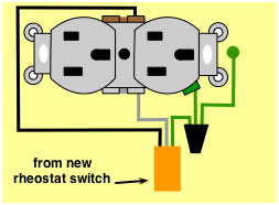
Connect the black wire from the new cable to the hot terminal on the receptacle. Connect the white wire to the neutral terminal and the ground wire to the ground on the receptacle and any grounding terminal in the outlet box. Install the receptacle in the horizontal outlet box.
#6 - Install the Crown
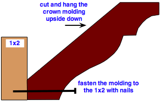
Measure and cut the crown molding using the surface of the 1x2 as the reference point. Cut it upside down and install it so the thick edge is against the 1x2. If possible use a pneumatic nail gun with 2 or 2 ½in. nails to attach the crown to the board. Otherwise, use a hammer and nail-sink to bury the nail heads below the surface so they can be filled with putty later.
#7 - Install the Remaining Moldings
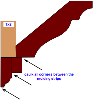
Install the stop bead on the wall just under the 1x2. Fasten it to the wall studs using 2 or 2 ½in nails driven along the center of the bead where they will be hidden by the square strip molding. Sink the nail heads so the top molding fits tightly without any gaps.
Butt the square strip against the bottom of the crown so it covers the nail holes in the stop bead. Use small brads about an inch long to fasten the strip to the stop bead. Sink the head on the strip and fill them with putty. Caulk the seams between all the pieces and between the stop bead and wall. Putty any remaining nail holes.
#8 - Install the Switches
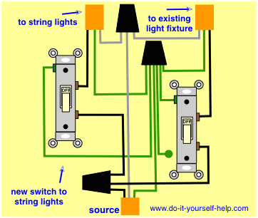
Reinstall the original switch and add a second one to the circuit to control the new lighting. We use a simple single-pole switch here and split the source to serve the two switches by splicing the hot wire to two pigtail wires using the proper wire gauge. Connect each pigtail wire to one terminal on each switch.
Reconnect the remaining wires on the original switch and then wire the new one by connecting it to the black wire running to the new receptacle. Splice the white wire from the receptacle with the other white wires in the switch box. Splice the new ground wire with the other grounds, and a pigtail. Run the pigtail wire to the new switch and add a second one for any grounding terminal in the box.
When all the wires are connected turn on the power to the circuit and test it using an analyzer or a lamp plugged into the receptacle. Make sure the switches are working and then plug the string lights into the receptacle and lay them out in the space behind the molding.
 Building Stacked Moldings