Switched Outlet Wiring Diagrams
by: Dale Cox
Check permit requirements before beginning electrical work.
How to read these diagrams.
This page contains several diagrams for wiring a switch to control one or more receptacle outlets including a split receptacle and multiple outlets wired together.
Wiring a Switch to an Outlet

This wiring illustrates a switched outlet circuit with the source and switch coming first. The hot source is wired to one terminal on the switch and the other connects to the black wire running to the hot terminal on the receptacle. The source neutral is spliced through to the receptacle neutral terminal and the source ground is spliced through to the grounds at the outlet.
Wiring a Split Switched Outlet

Here a receptacle outlet is split by removing the connecting tab between the two hot terminals. This splits the outlet so each half functions independently. Three-wire cable runs from the switch to the outlet, providing two hot wires to that location.
The source hot at the switch is spliced with the red cable wire to the outlet and a pigtail to the switch. At the receptacle, the red connects to the top half of the outlet. The black cable wire runs from the switch to the bottom half of the outlet. With this arrangement, the bottom half of the outlet is controlled by the switch and the top half is always hot. This is convenient if you want to have a hot outlet to plug in a clock or other device that needs constant power but still control a nearby lamp with the wall switch.
Wiring an Outlet to a Switch Loop

This wiring diagram illustrates adding wiring for a light switch to control an existing wall outlet. The source is at the outlet and a switch loop is added to a new switch. The hot source wire is removed from the receptacle and spliced to the red wire running to the switch. The black wire from the switch connects to the hot on the receptacle. The source neutral wire on the receptacle is removed and spliced to the white wire running to the switch and to a pigtail back to the receptacle neutral. At the switch, the neutral wire is capped unless needed to power a smart switch such as a new dimmer. This wiring is now required in most switch boxes as of 2011.
Wiring a Split Switched Outlet with a Switch Loop

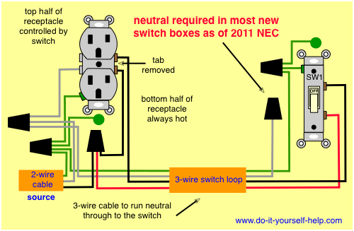
This diagram illustrates the wiring for a split half outlet controlled with a switch loop. The tab connecting the hot terminals on the receptacle is removed and the source hot is connected to the bottom half. The source neutral is connected to one of the neutral terminals on the receptacle. The white wire on the switch loop is used to carry current from the source to the switch and it is marked with black tape or paint to label it as hot. The black on the switch loop runs from the switch to the top half of the receptacle. With this arrangement the top half of the duplex is controlled with the switch and the bottom half is always hot.

This is an updated diagram for the previous circuit. Here the source neutral is spliced to the receptacle and to the white wire running through to the switch box where it can be used to connect a switch that requires a neutral such as a smart dimmer or timer. A neutral connection like this is now required in most new switch boxes as of the NEC code changes in 2011.
Wall Outlet Switch Wiring Diagram

Here a switch has been added to control an existing receptacle. The switch takes the hot from the middle receptacle here and 3-wire cable runs from there to the new switch location. The hot source at the outlet is spliced to the black wire running to the switch and the hot wires running to the other outlets in the circuit. The source neutral remains pigtailed to the neutral on the receptacle and the new neutral wire is added to the splice. Likewise, the new ground wire is spliced into the circuit at the receptacle. The red wire from the switch loop is connected directly to the hot terminal on the outlet.
At the switch, the black wire is connected to one terminal and the red wire is connected to the other. The neutral wire in the new switch box is capped with a wire nut unless it's needed for a smart switch or timer.
With this arrangement, all the other receptacles are wired directly to the hot source and the switch controls the middle outlet only. The white neutral wire in the new switch box complies with NEC 2011 requirements.
Wiring Diagram for Multiple Switched Outlets

This diagram shows the wiring for multiple switched outlets on one switch. The source for the circuit is at the switch and 2-wire cable runs to each receptacle outlet. At the outlets, each is wired using a pigtail splice to make the hot and neutral connections. With this arrangement, all the outlets will turn on and off at the same time.
 Wiring to Add a New Receptacle
 Light Switch Wiring
 Wiring for Combo Switches
 Wiring Wall Outlets
 Wiring Multiple Receptacles
 GFCI Receptacle Wiring
 Replace Switches and Receptacles