Replacing Electrical Receptacles and Switches
by: Dale Cox
Check permit requirements before beginning electrical work.
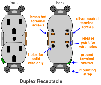
How to read these diagrams.
As of the 2011 NEC, most new and replacement receptacles must be tamper-proof. This requirement is designed to protect small children from injury by preventing the insertion of objects, other than electrical plugs, into the receptacle contacts. Some exceptions to this requirement include wall receptacles that are more than 62 inches from floor level and large appliance receptacles located out of reach.
An old switch can be replaced with the same type, or you can change a single-pole switch to a rheostat dimmer if it controls an approved light fixture. Older switches may not have a grounding terminal and there may be no ground wire present in the switch box. In these cases, if it's a grounded metal box, the grounding terminal on the new switch should be connected to it. Otherwise, a non-conductive faceplate should be used to avoid direct contact with the metal on the switch when operating the lights. See below for 2008 NEC on no ground wire in a switch box.
New wall receptacles and switches will have two types of contacts: terminal screws on the sides, and holes in the back. The screws may be designed to secure a hooked wire to the device when driven home, or they may be used to tighten a clamp around the end of a straight wire.
The holes in the back of the device are used for inserting a straight wire into an internal clamp. The holes will be labeled to indicate what wire size they can accept.
Both, switches and receptacles are available for 15 and 20 amp circuits, so be sure to use the proper sized replacement device for the circuit you are working on.
In an older dwelling, the devices and wiring may be outdated and you will find receptacles that are ungrounded or even ungrounded and non-polarized. Always use an appropriate type of receptacle to replace the existing one for replacement. For instance, don't replace an ungrounded receptacle with a new, grounded one if no ground wire is present.
2008 NEC on No Ground Wire in Switch Box
404.9 (B) Exception. "Where no means exists within the snap switch enclosure for connecting to the equipment grounding conductor or where the wiring method does not include or provide an equipment grounding conductor, a snap switch without a connection to an equipment grounding conductor shall be permitted for replacement purposes only.
A snap switch wired under the provisions of this exception and located within reach of earth, grade, conducting floors, or other conducting surfaces shall be provided with a faceplate of nonconducting, noncombustible material or shall be protected by a ground-fault circuit interrupter."
Light Switch Anatomy
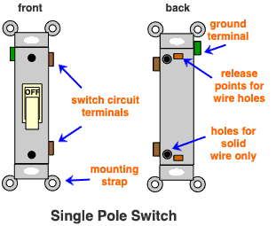
There are 3 basic types of wall switches you will encounter in most situations. A single-pole switch is the most common you will find and can be identified by two screw terminals, and in the case of new devices, a third one for ground.
The second most common type of switch found in residential buildings is a 3-way switch. These can be identified by three terminal screws and a forth, green screw for connecting a ground wire. A 3-way switch is used to control lights from two locations like at the top and bottom of a flight of stairs.
Another switch you may find in your home is a 4-way switch. These have four terminal screws and a fifth green one for a ground wire. Four-way switches are used between two 3-way switches to control lights from 3 or more locations. This can be handy if you have a large room with several entrances requiring light control from multiple locations.
Removing the Old Device
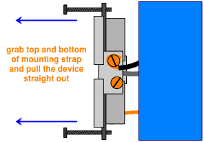
Shut off the electricity at the service panel for the circuit you will be working on. Test the circuit using a known working lamp or other electrical device to be sure it's off. Flip a light switch to be sure the bulb doesn't light, or use a volt meter to test the wires and confirm the circuit is off. Remove the cover plate and the top and bottom screws holding the mounting strap to the outlet box. These are long screws and easier to remove with a drill-driver if you have one.
Grasp the top and bottom brackets and pull the device straight out from the outlet box so you can reach the sides and back. If you will be disposing of the old device, completely remove the terminal screws. This will make it much easier to free the hooked ends of the wires. Leave the wires bent into hooks if you will be using the terminal screws to connect the new device. If you will be using the holes in the back, cut the wires right below the hook so you will have a straight piece to insert into the holes. Strip about ½inch of insulation off the copper to make the connection.
If the existing receptacle or switch is connected through the holes in the back, push a jewelers screwdriver or similarly shaped tool into the slot next to each hole to release the clamp pressure and pull the wire free.
Installing the New Device
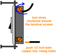
Attach the wires to a new switch connecting the hot source to one terminal and the wire running to the light to the other. On a receptacle, the black wire from the source goes on the hot, brass colored screws and the white goes to the neutral, silver colored screws. If there are two sets of wires on a receptacle, keep them in sets using the top terminals for one and the bottom terminals for the other set. Place the hooks so they point in a clockwise direction and the insulation runs all the way up to the screw. Don't leave any bare wire between the terminal and the insulation. Tighten the screws to clamp the wires down. The same goes for clamps that are tighten over a straight wire, there should be no bare copper showing.
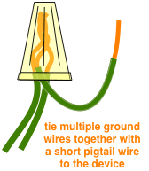
If you are using the holes in the back, push them into the proper holes until the clamp engages and locks them in place and there is no bare copper showing. Pull on each wire to be sure it is securely connected. Connect the ground wire to the grounding terminal on the device and any grounding terminals in the outlet box. If there are several ground wires, tie them all together with a short pieces of wire, known as a pigtail, to connect to the terminal screws. There is no hole in the receptacle or switch for the ground wire, only a screw.
Leave the device hanging free so it doesn't make contact with anything and test it to be sure the wiring is correct before installing it in the outlet box. Flip the switch on and turn the power back on at the breaker box to test the light circuit. Use a receptacle analyzer to test a receptacle for proper wiring. If there's a problem with the wiring, turn the power off again and correct the problem.
If the wiring is correct, turn the power off and install the device in the outlet box. Carefully fold the wires to fit into the box and push the device with your palm until it sits flat and is aligned with the mounting holes. Drive the mounting strap screws and shift the replacement of the device left or right as necessary to square it in the box as you tighten them down. Install the cover plate, turn the circuit back on and test the device again.
 Diagrams for Wall Outlets
 Light Switch Wiring
 Switched Receptacle Wiring