Wiring Diagrams to Add a Receptacle Outlet
by: Dale Cox
Check permit requirements before beginning electrical work.
How to read these diagrams.
This page contains diagrams to add a new electrical outlet to an existing circuit. Arrangements are included to use an existing receptacle circuit or lights and switch circuits as the source for a new wall outlet.
Wiring a New Outlet to Another Outlet

To add a new outlet to a group of receptacles already in place, splice the new wires to one set of wires on one of the existing outlets. Run 2-wire cable from the existing receptacle to the new outlet location.
In this diagram, each receptacle is wired to the next using the terminals to pass the voltage along so each has 4 wires, not including the ground, connected to it. To provide voltage to the new outlet, disconnect both black wires and both white wires from the most conveniently located, existing receptacle. Splice both existing black wires together with the black wire running to the new outlet and a short pigtail wire to connect back to the existing receptacle. Splice the white wires in the same way. Also, splice the ground wire from the new cable with the other ground wires in the outlet box.
Wiring Diagram for a New Outlet Off a Light Switch

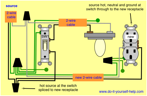
This diagram shows the wiring for a new outlet added from a light switch. The switch must have an always-hot wire for the source and a neutral wire must be present for the return path. This receptacle can not be added to a switch wired as a loop to control the light.
Here the hot source is spliced with a pigtail back to the switch and to the black wire on a new, 2-wire cable running to the new outlet. The neutral is spliced in the switch box to both the existing light and the white neutral wire to the new location. Lastly, the new ground wire is spliced with the other ground wires in the switch box.
Wiring a New Switched Outlet From a Light

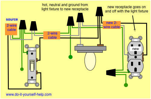
Here a new receptacle is added to an existing light fixture circuit creating a new switched outlet. The source for this circuit it at the light switch. The connections are made at the light fixture by removing the black and white wires from the light. The new outlet wires are spliced with each of these existing wires along with a pigtail wire to connect back to the light terminals. With this arrangement the new outlet will turn off and on with the light fixture.
Wiring a New Outlet to a Light Fixture

This circuit diagram shows the wiring for a new receptacle outlet connected at an existing light fixture where the source hot is at the ceiling box. A switch loop with an available neutral wire is used to control the light which complies with NEC 2011 requirements.
New 2-wire cable runs from the light fixture box to the new outlet location. The source hot is spliced to the new black wire and to the black switch loop wire. The neutral is spliced with the new white wire and a pigtail back to the light neutral terminal. The new ground wire is spliced with the existing ground wires in the ceiling box. With this arrangement the new receptacle is always hot.
Wiring a New Outlet Off a 3 Way Switch

In this diagram, an outlet is added to a 3 way light circuit where the source comes in before the switches. It is not controlled with the switches but is instead always hot. New 2-wire cable runs from the source 3 way switch box to the new outlet location.
The source hot wire is disconnected from the circuit at the switch box and the new black wire for the outlet is spliced in. Likewise, the neutral for the new outlet is spliced with the circuit neutral wires. The new ground wire is spliced with the other existing ground wires in the switch box. This addition has no effect on the existing 3 way switch circuit.
 Add a New Light Fixture
 Wiring for Two Outlets in One Box
 Wiring for Wall Outlets
 Wiring for Multiple Receptacles
 Wiring for Outlets Behind Baseboards
 Find an Electrical Source